Testing the action of the grease box once it was mounted under the bench – pretty satisfying. Now I just need to load it up with grease.
Grease Box in action
3

Testing the action of the grease box once it was mounted under the bench – pretty satisfying. Now I just need to load it up with grease.
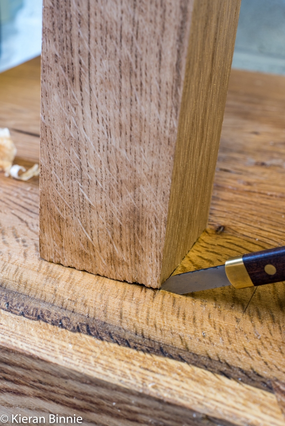
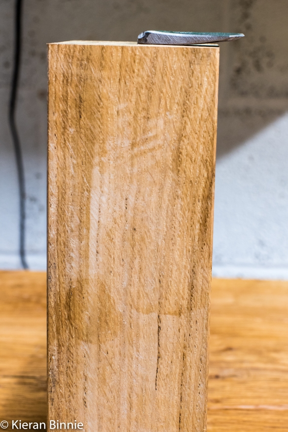
Paring the walls square
One of the bench details Roubo mentions in passing is a grease box, mounted under the benchtop. The engraving at Plate 11 shows a simple box, but on the whole there is not much time spent describing the grease box. Hand tool work benefits greatly from a lubricant for plane soles and saw plates, and regular readers will know that I use mutton tallow as my lubricant of choice. Adding the grease box mentioned by Roubo was high up my priority list when I started planning this build, and it turned out to be a very enjoyable, and quick, addition to the bench.
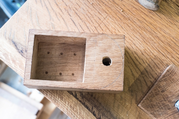
Hollowed out, and with the shaping marked in
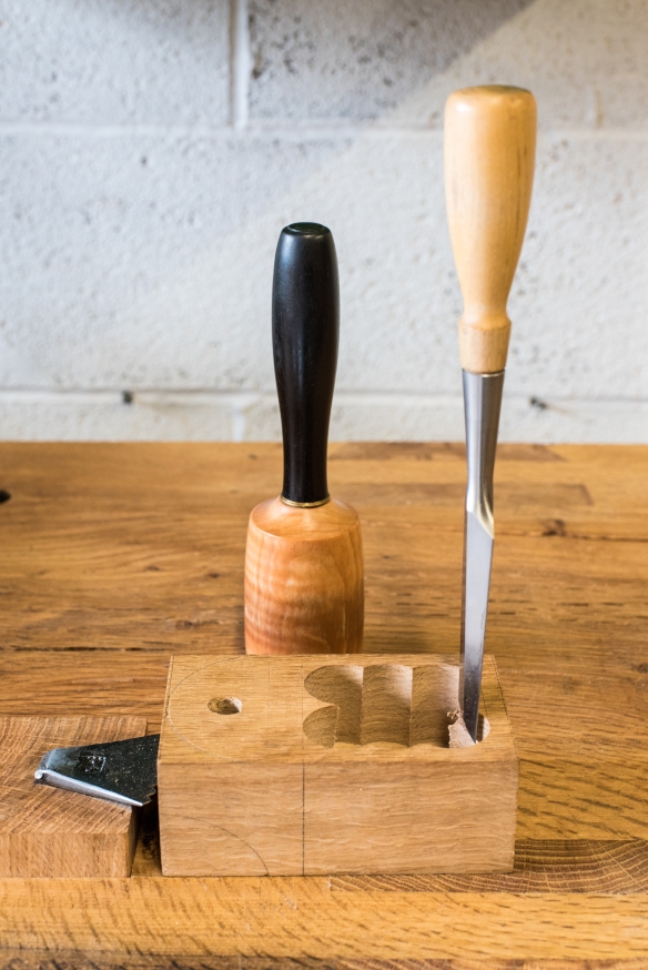
Roubo does not give any dimensions or specific details for the grease box. I decided to use an offcut from the stretchers, which I trimmed to length so that it measured 5 pouce long, three pouce wide, and 2 pouce thick. While this is a simple part of the build, the sequence of operations is critical if you are to enjoy easy workholding – carry out key operations in the wrong sequence and life will be that much more difficult. After laying out the grease compartment and the shape of the box, I drilled the mounting hole, as it was easier to hold the workpiece with a holdfast before the box was hollowed out and shaped. Another reason for this order was that I could then test the layout of the compartment by holding the grease box in place under the bench top with an auger bit through the mounting hole, and pivot the box out. Once I was happy with the layout and the position under the bench, I clamped the box to the underside of the bench next to the left-hand front leg, and drilled the pilot hole for the screw in the benchtop using the mounting hole in the greasebox as a guide.
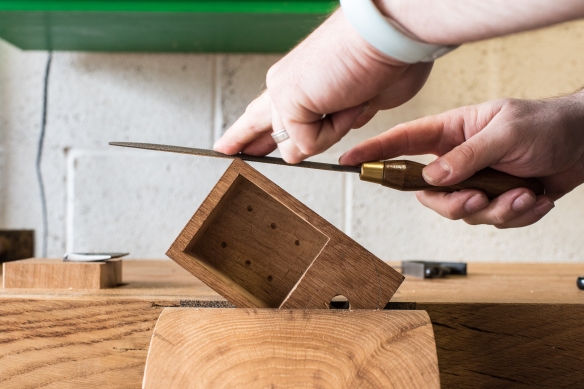
Rounding over the front corners with a 13 grain Auriou rasp
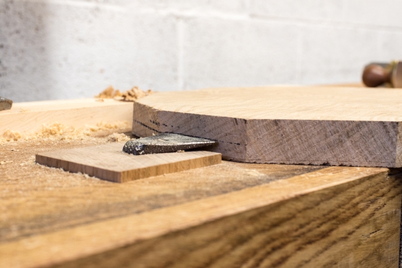
To hollow the box I used a forstner bit in my North Bros brace, as this removed material rapidly and the centre point leaves a much shallower divot than the lead screw of an auger bit. The walls of the box are 1/4 pouce thick, and I left a 1/2 pouce thick bottom. Counting the revolutions of the brace resulted in a pretty even box floor, following which I pared the walls flat and square with a wide chisel.
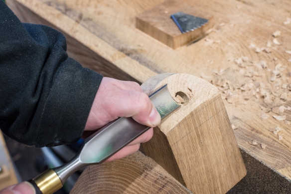
Hogging out the cutaway with a firmer gouge
Most of the work on the grease box was shaping it. I decided to make my grease box roughly the same shape as that shown by Roubo in Plate 11, with a rounded end, and a gentle cutaway under the mounting screw. After gently rounding the front corners of the box with an Auriou 13 grain rasp, I then shaped the rounded rear end with a 9 grain rasp (also by Auriou). The 9 grain rasp is aggressive but still very precise, and by working from each side to the apex of the curve, I was able to achieve a flowing curve quite quickly. The tool marks were removed with the 13 grain rasp and a quick rub down with sandpaper (the first time I’ve used sandpaper on the bench build).
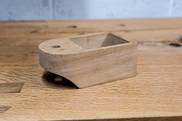
Shaped, and ready for oil
Shaping the cutaway involves working across the full width of the box. Instead of working across the full width straight away, I prefer to bevel one edge and rough in the curve on that edge before expanding the curve across the width of the box, refining as I get closer to the line. The 9 grain rasp roughed in the curve, and then I removed much of the waste using a wide firmer gouge to work across the grain. Once the curve was roughed in, I went back to the 9 grain rasp. Each Auriou rasp is hand-stitched for either right or left handed use, and is intended to be skewed across the workpiece (I visited the Aurio forge in 2016 – see posts here and here for more about these heirloom tools). However, ecause of the width of the box, I worked side to side, moving the rasp across the box instead of skewing it. This ensured that the curve was even across the width, and still removed material cleanly. Once the curve was shaped, I moved to the 13 grain rasp to remove tool marks, followed by sandpaper.
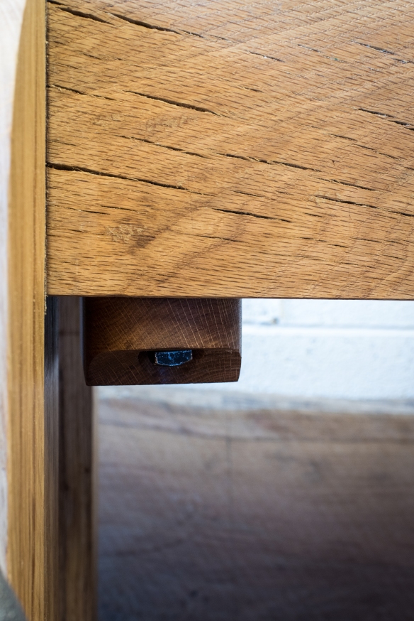
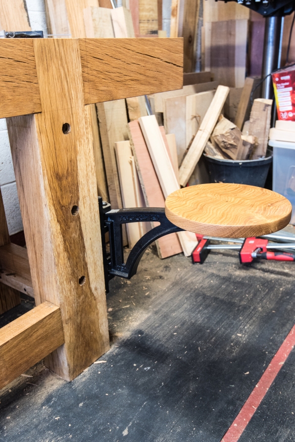
The grease box rests underneath the bench top, next to the front, left-hand leg and the leg vise
Once I was happy with the appearance of the box I gave it a coat of boiled linseed oil, and left it for 24 hours for the oil to dry, before mounting it under the bench using a 1/2″ x 2″ square headed lag screw and washer from blacksmithbolt.com – this will easily support the weight of the box. The mounting hole in the box is slightly larger than the width of the bolt, meaning that it pivots freely, and I also drilled a flat area to allow the bolt head and washer to seat cleanly on the cutaway. All I need to do now is order some more tallow (or possibly paraffin wax) and load it up.
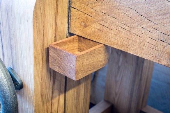
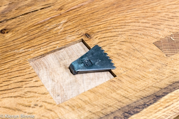
Rotated out, ready to be filled with paraffin wax or mutton tallow
The planing stop bites into the workpiece and holds it in place effectively
While the focus of this build has been on trying to hew as close to Roubo’s description of the French-style bench as far as possible, when planing my “Roubo” bench I decided I wanted to add a swing away seat by Benchcrafted. I find chopping dovetails, and some detail work, more comfortable when sitting at the bench instead of being hunched over it, and having a seat which is attached to the bench and folds out of the way, seems to be a space-efficient solution. I fitted the swing away hardware to the right-hand bench leg over the Christmas break, but hadn’t had an opportunity to turn the seat itself until this weekend.
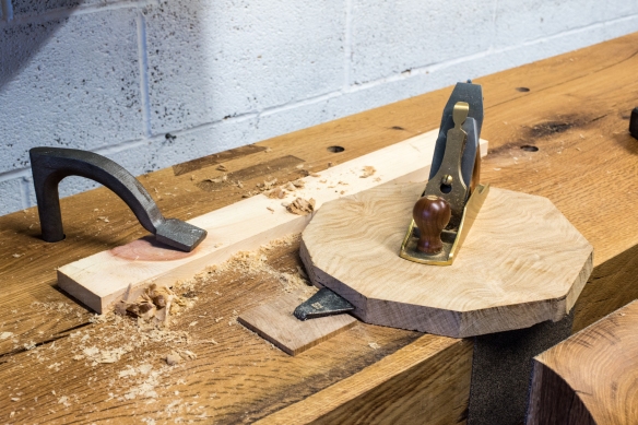
Planing the seat blank smooth
I had been saving an offcut of the oak slab I used for my Mortise & Tenon stick chair for the seat top, which meant I could keep to a single species for the whole bench. I cut the blank into a rough hexagon, about 12″ wide, and then planed it to 1″ thick. This also gave me a chance to test out the planing stop I fitted last week, and found that it gripped the workpiece very well indeed with only a sharp tab with a mallet to drive the workpiece onto the teeth of the stop.
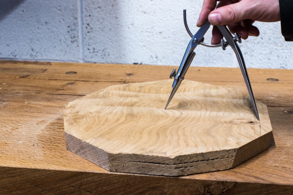
Marking out the diameter of the seat, on the underside
Once the seat was at final thickness I scribed an 11″ diameter circle on the rear side, and then removed some more of the excess material forming corners with a back saw, in order to reduce the risk of a catch on the lathe. I then mounted the lathe faceplate onto the rear of the seat, and slid the seat into position on the lathe.
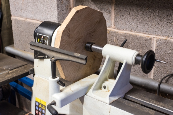
Turning the seat blank
This is the first time I’ve turned anything this year, and while a 11″ wide disc is about as simple as turning can be, it was immensely satisfying. The process of taking an irregular-shaped piece of wood and changing it to a perfectly round circle in a short period of time was remarkable, and I”m looking forward to turning some bowls and platters later over the coming months. To turn the seat I used an EasyWood roughing tool for most of the grunt work, followed by an EasyWood finisher to clean up the surface and to round over the corners a little. After drilling the holes for the mounting screws and mounting the seat on the hardware bracket, I applied a coat of boiled linseed oil to the seat top.
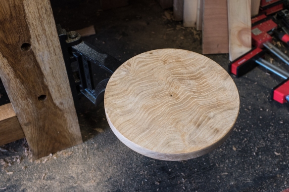
Fitted and ready for oil
This was a quite a simple stage in the build, but it was very satisfying to get another element of the bench finished in what has proved to be a very busy week. All that remains now is to make the grease box, and then to mount the shelves on the stretchers. Roubo is very nearly here.
The oiled seat, ready for use
Marking the final width of the tenon
I find it interesting how a lot of work can result in something very simple. And how simple does not always mean straight forward (or easy). At first blush, the planing stop is incredibly simple – a square mortise and a square loose tenon that fits the mortise. But that simplicity requires a lot of attention, and being prepared to fuss over the fit. The planing stop needs to be friction fit to the mortise – too loose and it will fall out of the mortise. Too tight and it won’t move at all, or worst case, will split the bench top. So, this most simple element takes time and patience. But that’s ok – I work wood because I like spending time at the bench. One day (soon, hopefully) the bench will be complete, and I’ll be using it to work other projects. All of that is a slightly round about way of saying that the planing stop is fitted and functioning as intended.

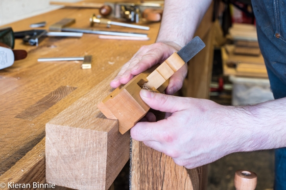
Using the No3 smoother to fine tune the fit of the tenon
Before I started fitting the stop itself I checked the mortise, and did a little tuning with a 1″ paring chisel to remove any bumps or stray lumps. With the mortise in good shape, I started to fit the tenon. I had deliberately left the tenon a few mm oversize, pending the final fitting, and so the first task was to take it down to size. At this point, the numbers are not important, what matters is that the stop fits the mortise well enough to move freely when encouraged with a mallet, but tight enough not to move otherwise. I presented the tenon to the mortise and got two perpendicular sides pressed nicely against the mortise walls. I had deliberately struck the layout lines for the mortise longer than necessary, as this helps to fit the stop. With the tenon located firmly against two sides, I marked off the final width on the remaining sides by dropping my marking knife into the mortise layout lines and nicking the side of the workpiece. I used these marks to set a marking gauge, and struck lines on the stop to identify the final width.
Chamfering the corners
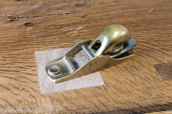
After planing the stop down to the marking gauge lines, I tested the fit in the mortise, and made fine adjustments with a smoothing plane until the stop moved 1/8″ with each mallet tap (thanks to Mark Hicks for his advise on fitting the stop and this tolerance as being a good indicator of appropriate friction). This took several rounds of fitting, and making small localised adjustments with the plane. I also knocked down the corners with the Phillychamfer plane, as these are a weak point and I did not want any stray fibres in the corners spoiting the fit. I had not squared up the top end of the tenon, and once it was fitting in the bench I planed it flush with a low angle block plane.
Planing the show-end flush and clean
After testing the movement of the stop through its full length, it was time to drill the hole for the toothed planing stop itself, which Peter Ross forged for me a few years ago. The planing stop had a tapered shaft with a square cross-section, and I drilled the holes while the tenon was fitted in the bench top. I bored the narrowest diameter hole needed first, which was the full length of the stop, using an auger in my North Bros brace. After this, I used engineering bits in an egg beater drill to drill the remaining, wider sections. The tip of the engineering bit follows the path of the pilot hole better than a spur and centre wood bit, which makes them very useful for reaming wider holes. Once the pilot holes were drilled, I hammered the stop into position, placing a saw bench underneath the wooden part of the stop to prevent it being driven through the mortise.
The toothed planing stop fitted in a 15″ long tenon
To prevent the teeth of the stop from sitting on top of the bench (and catching tools or fingers) when not in use, I knocked the stop as close to the benchtop as possible, and traced roung the teeth with a marking knife. After removing the stop from the mortise, I used a chisel to deepen my marking knife lines and a small router plane to remove sufficient material to allow the teeth to rest under the surface of the bench. This is a small detail, but one which did not take too long and which adds a nice point of interest (and functionality) to the bench.
Fitted and ready for use


While I was in a boring frame of mind after last week’s blog post, I bored out the waste for the planing stop mortise, using the same WoodOwl ship’s auger in my North Bros brace as I had for the holdfast holes. With 8 holes bored round the perimeter of the mortise, the middle portion of waste lifted out easily. The second feature of the holdfast drilling jig then came into play – the 90 degree face providing a useful surface to register the 1 1/2″ timber framing chisel on when paring the mortise flush without any undercutting.
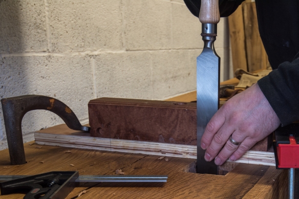
Paring the mortise flush with a timber framing chisel
The planing stop needs to be friction fit in the mortise, so that it can be easily adjusted with a mallet, and not so tight that is splits the bench top. Having a consistently sized mortise will make fitting the planing stop a lot easier, and also a lot less prone to seizing up (I hope). So some effort getting a clean mortise is definitely time well spent. I started by paring the to end grain surfaces perpendicular to the top of the bench, followed by the long grain sides. This sequence of work ensured that chopping the waste from the long grain would not result in a split in the bench top. I cut the mortise entirely from the top, as flipping a completely assembled Roubo bench sounded a lot like work. There was some minor blowout on the underside, but nothing any one will see, and certainly nothing that will impact on the integrity of the slab.
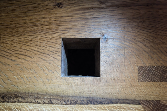
A square and true mortise
Once the mortise walls were pared clean I did a final sweep round the corners, which is invariably where junk collects. I did allow some slight undercutting in the corners, as the substantial sides and ends of the mortise will provide the gripping power on the planing stop, and relieving the corners ensures a good fit without reducing the necessary friction.

Squaring the planing stop
With a clean and plumb mortise, I started work on the planing stop itself. This was the first opportunity I’ve had to use the Benchcrafted Glide C vise since I installed it in the bench, and I was not disappointed – it combines sweet and smooth movement with a tenacious grip. Processing the planing stop in the vise with the big Lie-Nielsen No8 was a rock solid experience, and I’m looking forward to spending the rest of my life working with this vise hardware. Processing the planing stop was pretty usual fare – I trued up two perpendicular faces, testing for a 90 degree angle with the Vesper 4″ square, and then worked the remaining two faces from the reference surfaces. I left the planing stop a hair oversize at this stage so that I can bring it down to final dimension while I am doing the final fitting.
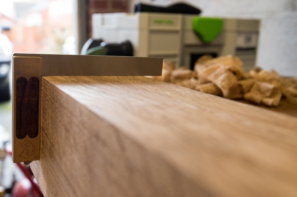
It’s not square until Chris Vesper tells you it is square
