Bridge to Nowhere… Part 2

DSC_0239

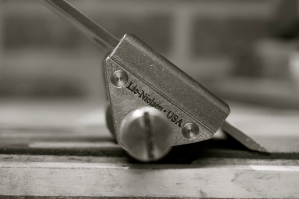
With less workshop time than I’d like to at the moment it is easy for some of the more mundane tasks to fall by the wayside, no matter how essential they are. I much prefer making tools blunt to sharpening them, but using a blunt tool is dangerous and results in sub-optimal work, neither of which are satisfactory. So I’m trying to make a concerted effort to spend my first 15 minutes as soon as I step into the workshop sharpening. No one (and I mean no one) sharpens as frequently as they should, but little and often is proving to be a sustainable and efficient way to keep all my edge tools in a state of readiness. The other advantage I’ve found is that 15 minutes at the oil stones serves as a mental cleanser to block out the demands of the outside world and get into the right mindset for precision woodwork.

IMG_2581

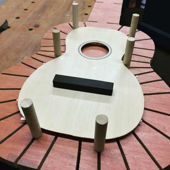
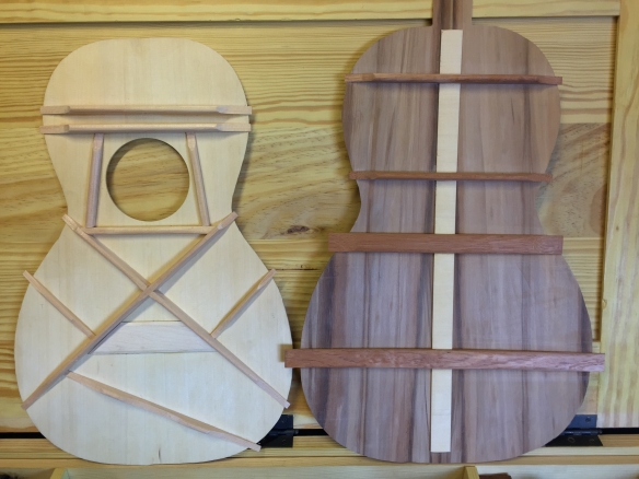
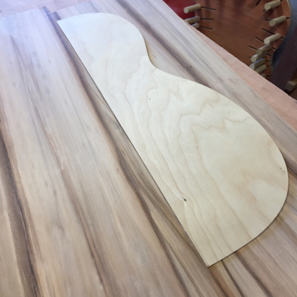
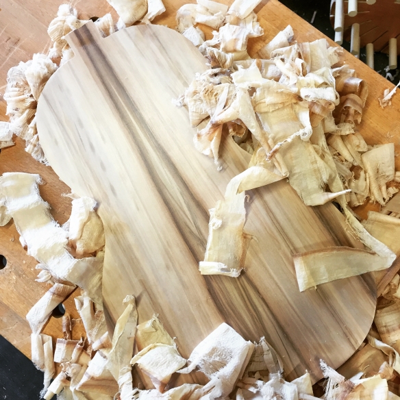
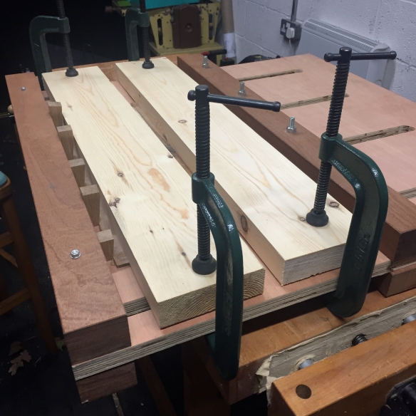
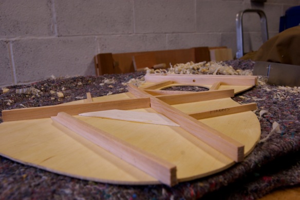
I hold the soundboard in a solera at this stage, mainly to keep it safe from knocks – having spent some time on the soundboard I want it to remain safe until the guitar is assembled!

Using sharpening as a meditative exercise has paid off this week, as I’ve been fitting the bridge to the parlour guitar. In my opinion fitting the bridge to the soundboard is both one of the most critical, and also most difficult, operations in building acoustic guitars. Critical because a solid joint is necessary to ensure that the string energy excites the soundboard efficiently (which creates the sound of the instrument), and also to preserve the structural integrity of the instrument. Difficult because a good joint depends on precisely matching the curve of the soundboard with a curve in the base of the bridge blank.

Some lutherie manuals call for the base of the bridge blank to be straight and flat at the point of gluing the bridge to the soundboard. This in my opinion is a fundamental mistake. The soundboard of an acoustic guitar curves across its width and length, thanks to the bracing. Fitting a flat bottomed bridge would at best force part of the soundboard out of the curve previously set by the braces, and at worst would result in a poor glue joint. Neither of these is a particularly promising idea, especially when you start to apply several hundred pounds of string tension to the bridge. And if you’ve taken the effort to plane a nice curve into all of those braces, why would you want to undo that good work at this point?

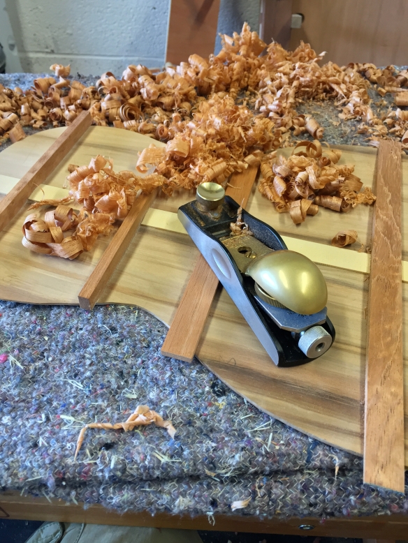
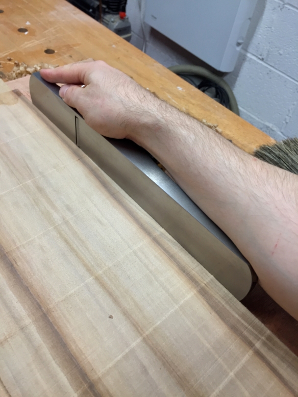
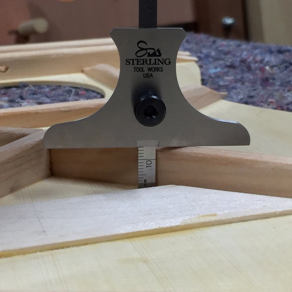
So instead I opt for the hard road of planing a precise curve into tough ebony or rosewood. What makes this even more fun is that the soundboard acts as a hydrometer, and will subtly change shape with humidity changes throughout the day. So not only are you using a tool designed to plane things flat to create a concave curve, but you’re trying to hit a moving target as you do so. Success is determined by using a super sharp block plane blade, taking very fine cuts, plenty of patience, and measuring a-plenty.

IMG_2576

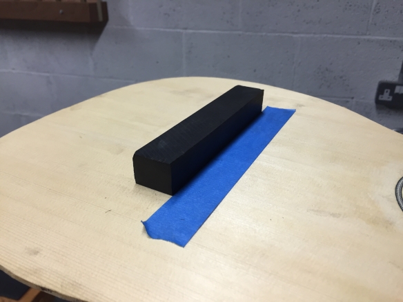
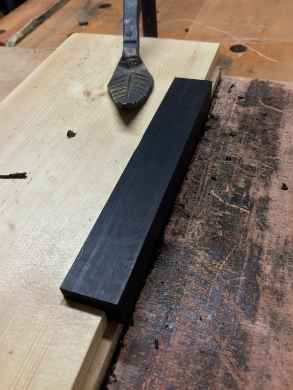
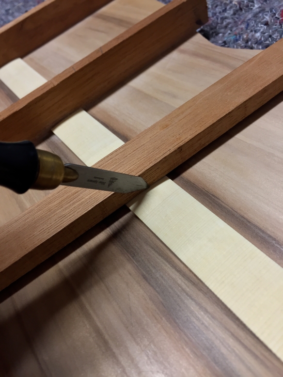
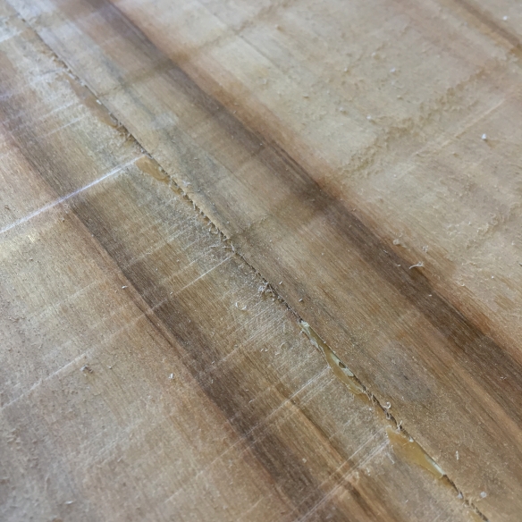
There are ways you can make this easier. A strip of low-tack painter’s tape on the soundboard makes placing the bridge in position easy (it’s important to use low-tack tape to avoid pulling grain fibres out of the soundboatd). I place the tape so that the rear edge falls along the front face of the bridge. Then when I come to check the fit of the bridge it is just a case of butting it against the tape, and easy placement without needing to reach for my ruler everytime means that I am inclined to check my progress more often.

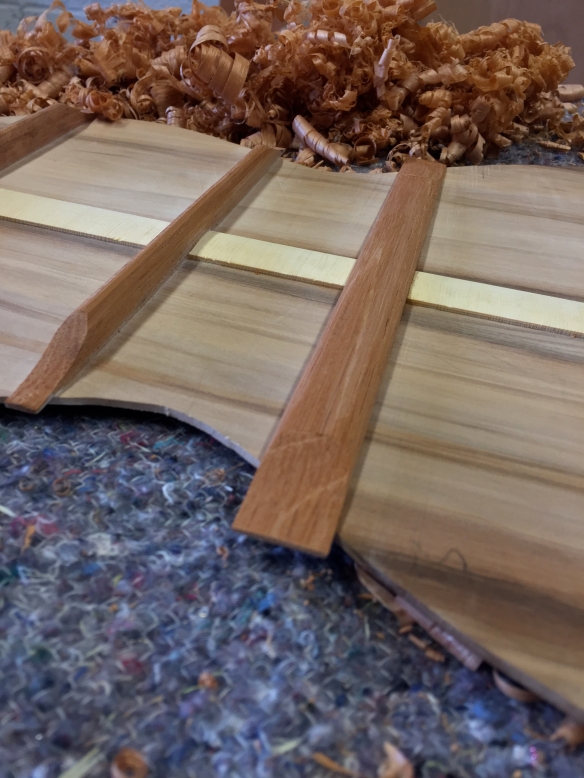
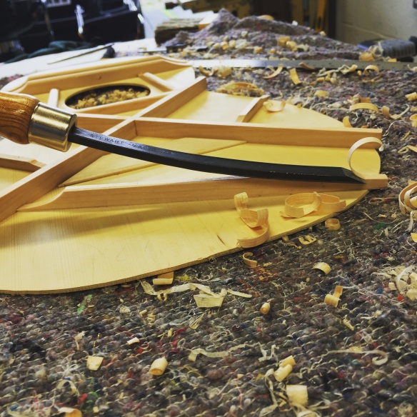
In terms of planing the curve into the bridge blank, I start by planing a gentle hollow into the middle of the bridge until the ends of the wings (which at first will be above the surface of the soundboard) touch the soundboard. Then it is a case of planing the curve across the depth of the bridge (between the front and rear faces). I do this by working across the grain, from each long edge to the middle of the bridge, with a very fine cut. It is important that the two long edges of the bridge form a good joint with the soundboard, but also that you avoid forming a hollow joint by removing too much material from between those edges, as most adhesives will not form a lasting bond across a hollow joint (and that is the path which leads to your bridge detaching itself from the soundboard under string tension).

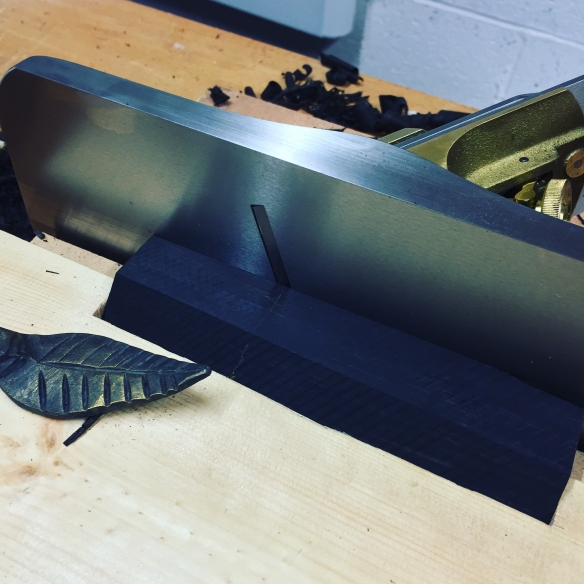
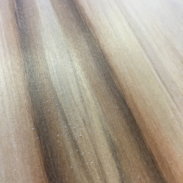
So plenty of checking is necessary. To check the fit, I place the corner of the front edge in position, holding it up to the light to ascertain how that edge fits. Then I do the same with the corner of the back edge. If the edge contact is good along the full width of the bridge on both edges, then I rock the bridge back from the front edge so that the base contacts with the soundboard. If material needs to be removed from the base then there is a subtle feeling like the bridge being cushioned as it makes contact, in which case it’s back to taking fine cuts across the grain. When the fit is right, there is a gentle “click” as both edges make contact with the soundboard without any interference from material between the edges.

IMG_2573

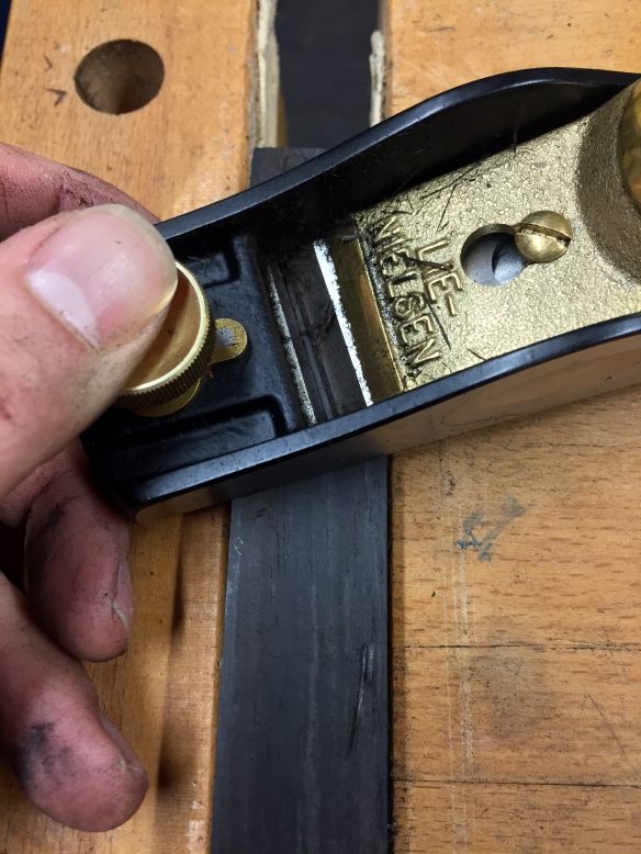
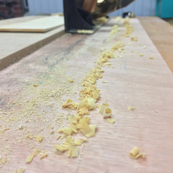
You can see from the shavings on the cap how fine a cut this plane is set to.

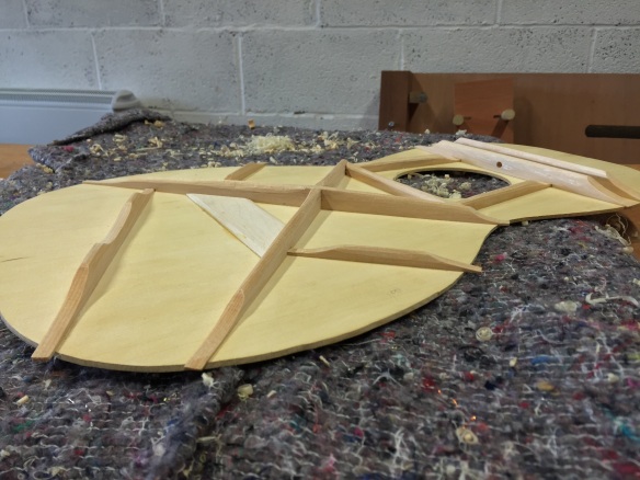
Fitting the bridge is not rocket science, nor does it involve arcane techniques or specialist tools. Just a lot of patience  and checking progress against the soundboard. The pay off is a solid joint which will result in an instrument with good tone and the strength to withstand string tension.

On a bridge with scalloped wings this would be the point at which I glue the bridge to the soundboard. However, as this bridge will have pyramid wings those need to be carved prior to glue-up, which I will cover in my next post.

Bridge To Nowhere… Part 1

or: The Enthusiasm and the Doubt

Due to other recent workshop commitments, and various demands on my time, the first opportunity I’ve had to work on the parlour guitar in 2016 came in late February. To be honest I find any lengthy period of time away from a significant build to be quite difficult – as I lose momentum it is easy to start focusing on the details of the build that I wish I’d done differently, and dwelling on any mistakes. The mind starts to play tricks, and convinces me that a perfectly good project is just glorified firewood – the enthusiasm starts to be replaced by a lingering self-doubt, and the incomplete parts of a project seem to taunt me. They say that sharks die if they stop swimming, and in a way large builds in the workshop can face a similar danger. I’m sure I’m not alone in feeling like this – most woodworkers I know have had a crisis of confidence over a big project, normally at a critical stage in the build (although there is the distinct possibility that I’m just a nut job). The best way I’ve found to respond to the mind’s treachery is to double down on the stalled project, because inevitably the project is in much better shape than I remember it and those catastrophic errors are simply not present.

So it was starting to go with the parlour guitar but fortunately getting stuck back into work, even on the mundane task of preparing an ebony bridge blank, was enough to dispel the growing self-doubt and get this build back on track.

The bridge of the original 19th century parlour guitar, on which this instrument is based, was 22mm deep with a straight saddle. Intonation on fretted instruments is always something of a compromise, but to my ears a straight saddle represents a compromise too far, so I decided to widen the bridge a little to allow for a compensated saddle. Increasing the bridge depth to 25.4mm gave me the necessary extra real estate without making the bridge look too heavy given the small body of the parlour guitar. The width remained at 149mm, as per the original design. I’ve always been a fan of the early Martin pyramid bridge design, but I’ve never had the opportunity to carve a pyramid bridge for any of my guitar builds. The pyramid wings will suit the parlour guitar’s aesthetic perfectly, so instead of the scalloped wings of the original guitar I’ll be carving pyramids for this instrument, which I’m greatly looking forward to.

IMG_2503

The bridge blank secured on the shooting board by a 5-minute jig

Securing small work pieces can be tricky, particularly when it comes to planing small pieces on the shooting board. My solution for this was to make a simple fixture to hold the bridge blank in place. I marked out a recess 20mm deep and 174mm long (the length of the bridge blank) on a large piece of 6mm thick scrap pine. I defined both ends of the recess with my carcase saw, and while I was at it made a couple of relief cuts across the width of the recess. It was then simply a case of knocking out the waste with a 1″ chisel and mallet. The bridge blank then pressed tightly into the recess, and the larger pine piece was easily secured on the shooting board by way of a holdfast. The tight fit of the bridge blank meant that the work piece did not slide under pressure from the plane, which makes for a much less frustrating experience.

IMG_2492

The Lie Neilsen No.51 shooting board plane and hold fast by Black Bear Forge are a fantastic combination

My main concern when shooting both long edges of the bridge was for a straight cut the length of the work piece, and which was bang on 90 degrees to the bottom of the bridge blank, with no undercutting. At this point I’m less concerned about the top surface, as this will be shaped once the bridge is fitted to the soundboard, but the bottom, front, and back all need to be perfectly square to each other. In the past I’ve used my Lie Neilsen 212 small scraper plane to dimension blanks, but for this bridge I wanted to see how the larger No.51 fared for shooting smaller work pieces. Needless to say, with a freshly sharpened blade, some careful setting of the blade’s lateral position, and the bridge secured in the jig, the large No.51 made relatively easy work of what can be quite a fussy job.

IMG_2518

My 12″ Bad Axe carcase saw is the perfect lutherie saw, here you can see the guide kerfs prior to trimming the bridge to length

With the long edges trued up, I then cut the bridge to length.  For this I struck a line for the first end on all four sides of the blank with a sharp marking knife, before trimming the blank using my Bad Axe 12″ carcase saw. I wanted this cut to be as accurate as possible and to need minimal clean up. This saw leaves a very good finish behind, so the only issue was getting out of the way of the saw and letting it cut straight and square. For critical cuts like this I prefer to make a shallow kerf on each of the four sides of the work with the saw, just to the depth of the saw teeth. When I come to cut the full depth of the work, the kerf creates a path of least resistance which the saw follows. The result is a square and true cut. With the first end trimmed I then struck marking knife lines 149mm along the blank for the other end, and having established my guiding saw kerfs on all four sides of the blank, trimmed the bridge to final width. Some gentle clean up with a 13 grain Auriou rasp and a Bahco smooth cut file, removed the saw marks, and the bridge is now ready for the gluing surface to be curved to match the curvature of the soundboard. But you’ll have to wait for my next post to read about that…

The End of Year Round-Up: 2015 edition

Is December already drawing to a close? I can scarcely believe that it is now time to start penning the end of year review, list my favourite albums of the past twelve months, and compile the traditional end of year mix cd. 2015 has genuinely disappeared in the blink of an eye. I suppose this is to be expected given all that has happened; the relocation from Bristol to Birmingham, buying and decorating a new house (phase 1 of the decoration saw 5 rooms decorated and completed, and phase 2 will be commencing in January), and becoming a father. I’d like to think that the above constitutes a reasonable level of activity.

IMG_2213

The parlour guitar build has been the main focus of 2015

Amongst all of this, I also found time to set up a new workshop, make some shavings, and keep writing. The new workshop has turned out to be ideal, and having given myself some time to settle into the new space I have made a few changes and additions since my original workshop tour, which I will write about separately. In terms of projects completed, 2015 is a little thin on the ground, although a lot of progress has been made on the parlour guitar, and I should be in a position to assemble this guitar in the next couple of months. I also managed to secure a new paying commission (the Mystery-Caster) and came close to bagging a paying commission from one of my favourite musicians (in the long term I’m hoping this one will still come to fruition).

2015 saw seven of my articles published in Furniture & Cabinetmaking, and the blog has had nearly twice as many views when compared to 2014, as well as introducing the new “Getting to Know…” feature (which I hope to continue into 2016).

IMG_0809

Peter Follansbee contemplates swiping my Hieronymus Bosch print Docs…

I had the pleasure of meeting both Peter Follansbee and Tom Fidgen, as well as taking Roy Underhill’s Woodworking with Thomas Jefferson class. Learning from Roy for a week was an incredible experience, and helped to develop all manner of parallel skills. Peter, Tom and Roy are not only incredibly knowledgeable, but also very generous with their knowledge, and I highly recommend taking a class (or simply just chatting with them) if ever the opportunity presents itself.

IMG_0882

Roy and Esmerelda become acquainted.

The other highlight of the year was of course exhibiting at the European Woodworking Show in Cressing Temple, and it was wonderful to get to meet so many inspiring makers and tool manufacturers, as well as people who read the blog (or my articles), and to spend two days chatting about woodwork face to face. Thank you so much to everyone who came and said hello during the two days.

Chris Schwarz

The “Community Is…” project in many ways defined 2015 for me. Thanks to all the contributors (including Chris Schwarz – pictured here)

And this very neatly brings me to the real highlight of 2015. Which is not projects built or achievements unlocked, but rather the sense of community in the woodcrafts. Lutherie always used to be a very solitary activity for me, but particularly over the past 12 months the online community through Instagram and the blogosphere, then reinforced through events such as EWS, has meant that I find myself within a wider community of craftspeople. And this has had the effect of enriching my time in the workshop, situating my work within broader practices and traditions, and providing new opportunities to learn and question. The community is made up of so many wonderful craftspeople that mentioning individuals seems like a foolhardy endeavour. However special mention must go to James McConnell whose Daily Skep blog debued this year, and is rapidly becoming one of my favourite woodwork blogs(seriously, I read James’ blog and wonder if there’s any point in me writing anything ever again). Again, EWS provided a wonderful opportunity to put faces to names and to connect with members of the woodworking community in person.

IMG_1422

Finally meeting Vic (Minimalist Woodworker) in person was one of the highlights of EWS

Looking forward to 2016, there will be more articles in Furniture  Cabinetmaking, in addition to which I hope to be able to announce a very special article for another publication in the coming months. In the workshop, my focus will be on finishing the parlour guitar, and also building the Mystery-Caster, both of which will be covered in detail on this blog. A number of teaching opportunities have presented themselves, and consequently there is also the possibility that I will be let loose on unsuspecting woodwork students – more details to follow once I have them. So plenty to keep me occupied, and 2016 is shaping up to be a very exciting year!

And to finish where we started, my top five pick of new releases from 2015 (in case anyone was wondering) in order, are:

  1. Banditos – Banditos
  2. Nashville Obsolete – Dave Rawlings Machine
  3. Edge of the Sun – Calexico
  4. Meta-Modern Sounds in Country Music – Sturgil Simpson
  5. No Cities To Love – Sleater-Kinney

Happy New Year, dear reader, catch you in 2016!

The Justin Timberlake Edition – Bringing Bracing Back

The pop culture puns aren’t getting any better, but they are definitely here to stay. I am so terribly sorry, gentle reader.

IMG_2198

The final stage of work for the parlour guitar back was the bracing. This guitar has a 4.5mm curve across the length, which works out to a little over 16 foot radius. As with the soundboard, I don’t curve each brace by the full extent of the curvature, or even by the same amount. Instead, I mark the full curve on the bracing plan for the back, along with a flat centreline. The point at which the top edge of each brace intersects with the centreline and curve line indicates the level of curve needed for that brace.

The parlour guitar is something of a departure for me, as previously all of the back braces would be the same dimensions for a given guitar. However, the 19th centure parlour guitar on which this current instrument is based had two different sized sets of back braces. So (counting from the heel of the guitar) the first two braces were 8mm wide, while the third and fourth braces were 20mm wide. It is always good to experiment, so I decided to stay true to the original and follow those dimensions rather than do what I have always done before.

I use cedrella for all of my back bracing needs, and once I had milled the stock to the required dimensions it was then a simple job of shooting the correct amount of curve using my No.5 bench plane and the “magic point” method I wrote about previously.

IMG_2179

Marking the back edge of the slot based on the width of the actual brace material – no rulers needed!

Before I could fit the braces it was necessary to bring the cedar reinforcement strip on the back joint down to height, and also cut the slots for the braces. A low angle block plane made short work of planing the reinforcement strip down to 2mm heigh, and also introduced a gentle camber across the width of the strip which was a pleasing visual touch. To slot the reinforcement strip for the braces, I measured off the front edge of each brace from the plan, and kerfed this line into the reinforcement strip with my marking knife. Where a snug fit is required, I prefer not to rely on measurements of workpieces, and instead let the work itself determine the width of the slot. To do this, I hold the marking knife in its kerf and place the brace against the flat of the knife blade. The marking knife can then register against the back edge of the brace to mark out the correct slot width. The two knife kerfs are deepend with a 1″ chisel, and the waste removed with a sharp narrow chisel. This method allows for any minor variatons in the width of the braces and ensures that I get a good tight fit everytime (it also means I don’t have to worry about too many numbers, which is always a relief).

IMG_2183

And clearing the waste with a 1/4″ chisel

Because the braces were of differing heights, I decided to do the glue-up in two stages. It is possible to shim lower pieces on the go bar deck, but it adds another variable not to mention unwelcome faff. So I took the easy route of doing a two stage glue up. A bracing cradle was made out of ply shims, as I did for the soundboard last month, and the thin protective ply mat was placed between the cradle and the back to prevent the cradle denting the show surface of the back. The first set of braces were then glued in and left overnight, before adjusting the ceiling height of the go bar deck and gluing in the second set of braces.

Once the glue had cured for all the braces, I bought them down to height using my Lie-Neilsen low angle block plane. The narrower braces offered a good balance of stiffness verses resonance at 13mm heigh, while the two wider braces were reduced to 7mm in height. Assessing the correct height was (as always) a case of flexing the back gently and listening to the tap tone change as the bracing height reduced. My new Sterling Tool Works depth gauge is rapidly becoming indespensible for checking brace height accurately and swiftly. I then profiles the braces using a combination of block plane and the small (25mm) thumb plane. The narrow braces were given a domed profile, while the two widers braces have a gentle camber. Each end of the bracs was then scalloped over 35mm of length, bringing them all down to a height of 1.5mm.

IMG_2207

Here you can see the difference between the narrow (tall) and wide (squat) back braces

Comparing the tap tone of the back to that of the soundboard suggested that some fine tuning of the soundboard would be beneficial. I increased the amount of curve on each of the lower X brace legs, by 1.5mm, and reprofiled both legs. The scallop in the middle of the tone bar was also deepened by around 0.5mm, and this minor work livened up the soundboard sufficiently.

The back is now complete and can be put aside until the guitar is assembled in the new year.

IMG_2213

The lid of my Anarchist’s Tool Chest makes for an ever-present photograph backdrop

Back to Work

IMG_2071

Marking out the body shape

Having surfaced the Red Gum for the parlour guitar back, my next task was to cut it to shape. I cut acoustic guitar backs 6mm oversized, to account for the thickness of the sides (plus a litte spare for good luck) when gluing the body together, and so I marked out the shape of the back in two stages. The first stage was to trace around the plywood body template with a pencil, to establish the size and shape of the soundboard. I then traced around the template again, this time using dividers set to a 3mm spacing. This created a fine scratch line in the surface of the work 3mm outside the pencil line. I cut to this scratch line with a fretsaw, resulting in a back the same shape as the soundboard, but oversized as intended. I also left a large square tab at the end of the upper bout, so that the back forms an integral heel cap with continuous grain.

IMG_2109

Thicknessing the back

Thicknessing the back was very much the same process as it was for the soundboard. I used calipers to mark off the thickness of the work every inch or so, and then planed down the highspots using a combination of my No.8 jointer to remove the bulk of the material, and then a low angle block plane for fine tuning, until the back was a consistent thickness of 2.95mm.

IMG_2117

End grain shavings from the yellow cedar reinforcement strip

It is common to reinforce the glue line of acoustic guitar backs by using an off cut of the soundboard, orientated with the grain running from side to side so that the grain acts as stitches across the joint. I shot the first edge of the yellow cedar reinforcement strip before I had cut the strip to size, as the large off-cut from the soundboard was easier to hold than a small strip would have been, particularly as a narrow strip is likely to deflect under pressure from the plane. This also gave me an opportunity to try out my new Lie-Nielsen No.51, which predictably excelled at shooting the end grain of the cedar (although it was ridiculously over specified for such a simple task – I’m looking forward to trying it out on some much more demanding furniture work soon). With one edge straight, I then cut the strip slightly over width, and shot the other edge straight until the strip was 20mm wide. To prevent the narrow strip from deflecting while shooting the second edge, I clamped the remaining soundboard off-cut to the shooting board and trapped the reinforcement strip between the larger off-cut and the plane.

IMG_2102

The surfaced and thicknessed back

The reinforcement strip will ultimately be planed down to 2mm in thickness, but for ease of workholding I glued it to the back while it was still at full thickness (around 5mm thick). The strengthening strip was glued in using go bars – I always love how for this operation the line of go bars look like the line of a sail!

IMG_2128

Fitting the reinforcement strip using the go bar deck

The 100th Post Extravaganza

So this is my 100th post on the blog. I didn’t really expect anyone to read this blog when I started writing nearly two and a half years ago. Nor did  I really think about whether I would reach 100 posts and still be going strong. So 100 posts feels like a milestone worth celebrating. Maybe there will be whisky.

IMG_2067

The surfaced Red Gum back for the parlour guitar

With the parlour guitar soundboard braced, I’ve now turned my attentions to the back of the guitar. I am using a very nice set of American Red Gum, purchased from the nice chaps at Brook Guitars, for the back and sides of this guitar.

The process for gluing and surfacing the back plates is the same as for the soundboard (which I have written about previously). So, jointing the plates on a long grain shooting board, gluing them in the thin panel jig, and then surfacing with a bench plane set to a fine cut. But just because you have carried out a certain process before doesn’t mean that you shouldn’t give it serious consideration the next time you come to it, as there are always ways to improve either the end result, or the efficiency in reaching that result.

Jointing the soundboard and back for the parlour guitar are a case in point. Ordinarily I use my No.5 bench plane for preparing this joint, but for the soundboard on this guitar I decided to experiment by using the No.8. It is after all a jointer plane, so this sort of work is what it excells at. As a comparison, I jointed the back plates with my Clifton No.5. Surprisingly, I found it a faster process to get a solid joint with my No.5 than the longer No.8. There are, I think, several reasons for this. Firstly is that the joint on a soundboard or back is determiend by the grain pattern, and consequently is rarely perpendicular to the top edge of the plates. For this reason, I use a slightly different technique for shooting the joint than I would for, say, shooting the end grain of furniture pieces square and straight.

IMG_2055

This grip is how I joint soundboards and backs using my No.5 bench plane

When shooting the joint for guitar plates, the fingers of my right hand are imediately in front of the mouth of the plane, while my forearm rests along the side of the plane. The egde of work piece hangs over the shooting board. When shooting the joint I attempt to plane a concave curve, with pressure in the first section of the cut being exerted by my fingers. The latter half of the cut is then made with the pressure coming through my forearm to the heel of the plane. This is contrast to an end grain shooting board, where the raised edge of the shooting board would guide the plane to a cut that is square to the top edge of the workpiece.

The smaller body of the No.5  is much easier to steer with the forearm compared to the No.8, and I achieved a solid joint in slightly less than half of the time taken for the soundboard. It was then a matter of clamping the jointed and glued plates in the thin panel jig. The No.8 is a wonderful tool, and one which gets a lot of use in my workshop, but for this specific task the No.5 remains my go to solution.

IMG_2060

The Red Gum back in the thin panel gluing jig

Cleaning the glue line on a soundboard or back is simultaneously thrilling and a little terrifying. When first out of the jig the squeeze out and rough sawn timber gives the glue line a decidedly rough appearance which doesn’t provide any hint as to how good the joint itself is. As the workpiece is surfaced, the glue line is cleaned up and starts to reveal whether the joint is good and tight or whether there are any hidden voids.

IMG_2066

The glue line before any clean up.

This particular set of Red Gum was interesting to work with, as the plates needed to be offset in order to match the grain. However, the timber cleaned up very nicely straight off the plane blade, and the grain is really striking. Next time around (on post 101!) I’ll look at cutting the back to shape and thicknessing it.

IMG_2070

The same glue line after clean up. There is no visible line, and the only way to spot the joint is to count the grain on either side.


Brace Yourself… Part 3

If bracing is one of my favourite elements of building acoustic guitars, then shaping and profiling the braces is one of my favourite elements of the bracing work. This is the moment when you really start to craft the tone of the instrument by removing material from specific points of the braces, and shaping them to a final profile that is pleasing to both the eye and the ears. As I’ve mentioned before, shaping the braces is an act of juggling structural integrity and acoustic resonance, and ultimately it comes down to feel, using your ears, and understanding how string tension is applied to the soundboard. Numbers alone are of very little use here!

DSC_0105

The braces at nominal height, but before any shaping work

With the braces all now glued to the soundboard, I planed the transverse and X braces down to their nominal height (13mm and 14mm respectively). This gave me the first opportunity to assess the effect of the bracing on the tap tone of the soundboard, and as expected the bracing at this point was too heavy, meaning that the soundboard did not resonate as much as I would like. But no bother, as there was plenty of material still to be removed.

IMG_1908

Checking the height of the braces with a Sterling Tool Works depth gauge

Broadly speaking, the area of the soundboard from the soundhole up contributes less to the sound of the guitar, but is critical for the structural integrity of the guitar. The braces in this area are therefore left heavier than the area from the bridge and below, as this lower area is the part of the soundboard that makes the largest contribution to the sound of the instrument.

My first step when tuning the soundboard braces is to shape the X braces. There are a number of options available here, including scalloping the lower legs of the X, or planing a gentle curve across the length of each X brace. I prefer to curve the X braces rather than scallop them, and my tool of choice for this is my trusty low angle block plane. The lower legs of the X brace had the most material removed, with the very end of each brace curving down to 3mm in height, while only a very gentle curve was planed into the top legs of each brace so as not to reduce the structural strength of the soundboard round the soundhole and upper bout. All the time while planning the curve into the X braces (and in fact removing any material from any brace) I was checking my progress first by gently flexing the soundboard across its length, and also holding it between forefinger and thumb and tapping the lower bout to assess how responsive the soundboard was. This is something that comes with experience, but essentially I listen for the point when the tap tone starts to open up and resonate. As you get closer to this point it is important to progress very cautiously, as removing too much material can loosen the soundboard up too much, which can pose the risks of both the instrument folding under string tension, or developing a flabby bass heavy sound with little definition between notes.

IMG_1872

Carving the taper for the end of the tone bar using “Old Bendy” – a curved chisel

Next I tapered the ends of all of the braces, as I had previously done for the ends of the finger, tone, and soundhole reinforcement braces where these connected with other braces. I carve a taper of just less than 1/3 of the length of each brace , save for the X braces where the taper is roughly 1/6 of the length of the brace, and the finger braces where only 1/4 of the length is tapered. The taper results in the tip of each braces brace being reduced to 1.5mm in height. These tapered ends fit into the kerfed linings when the guitar is assembled.

Having removed further material by carving the tapers at the end of each brace, I was getting closer to a point where the soundboard had the desired responsiveness. Taping and flexing the soundboard I felt that the transverse braces only needed minor tweaking, and shaving a further 0.5mm off their nominal height brought them down to a good final height. The height of the tone brace was also lowered a little from the nominal height of 13mm

The curve on the X braces and tweaking the height of the transverse and tone braces had opened the tap tone up, but I felt there was a little more to come off. Rather than increase the curve of the X braces any further, my next step was to shape the profile, or cross section, of the braces. Some builders profile the braces after they have tuned the bracing for the optimum balance of strength and resonance, but I prefer to use the profiling as a means to tune the braces. Because after all, profiling involves removing yet more material from the bracing. The profile is a matter of personal preference, and some builders use a gentle rounded profile while others aim for a more pointed, almost gothic, shape. There really is no right (or wrong) answer, providing that the optimum amount of material is removed from the braces, so I profile the braces until I am happy with the appearance and the tap tone indicates that no further material should be removed.

IMG_1271

The 25mm long thumb plane I use for all my brace profiling

I profile the braces using a 25mm long thumb plane, slowly knocking off the corners of the braces and gently bringing them to the desired shape. A sharp ½” chisel is also useful for working into tight spaces between braces, both used bevel down, and bevel up with the chisel back pressed against the line of the brace. I prefer to leave my braces shaped from the plane and chisel blade, rather than sanding out any tool marks. Again this is personal preference, and while I like to finish the exterior of the guitar to as high standard as possible, it pleases me to think that internally there are some signs that my instruments have been made by hand rather than machine. The braces for this soundboard ended up with a gothic arched profile, which looked sharp and also lightened the bracing a little further.

Having profiled the braces, the resonance of the soundboard was very close to where I wanted it, but not quite 100%. The final touch was to gently scallop the middle of the tone bar by 3mm, and this resulted in a lively and responsive soundboard which still had plenty of stiffness. It just goes to show how a little spruce can go a long way, when you consider that the scalloping did not remove much material from the tone bar but definitely had a significant impact on the sound. Scalloping after the profiling leaves a nice crisp transition between the different cross sections of the tone bar, although again there are no hard and fast rules about how to do this and some makers will scallop before they profile the braces.

The only remaining task for the soundboard is fitting the bridge (which is in effect the final brace) and I will be writing about this soon.

IMG_1915

The finished soundboard bracing

Brace Yourself… Part 2

DSC_0094

Once the glue for the flat braces had cured I broke the soundboard out of the go bar deck and planed the flat braces to their nominal height. The finger braces and soundhole support braces are 8mm high each, while the tone bar has a nominal height of 13mm. Each of the nominal heights may change a little when I carve and shape the braces to achieve the desired sound, but at this stage reducing them to a nominal height is sufficient, and also easier to do before the curved braces are fitted. To protect the surface of the soundboard when carving and planing the braces I use a thick removal blanket on top of the workbench.

The tone bar (in the foreground) and finger brace (in the background), having carved the ends to fit into the X brace.

The tone bar (in the foreground) and finger brace (in the background), having carved the ends to fit into the X brace.

The tone bar and finger braces fit into slots on the X braces, and two of the soundhole supports similarly fit into slots on the lower transverse brace. So the next task was to taper the ends of the tone, finger, and soundhole braces to a height of 1.5mm, ready to fit into the curved braces. Much of the waste was removed using a 1/2″ chisel with the bevel down, and then the final  curve faired up using a curved chisel.

Many builders curve their braces by sanding them on a radius dish, which then doubles as a clamping caul in the go bar deck. However I still use the method taught at Totnes, and shoot the curvature for the X braces and transverse braces on a shooting board using a jack plane. For this guitar I am using a 3.5mm curve for the soundboard (which equates to a 23′ radius, if my admittedly shaky maths is to be believed). The X braces have the full extent of the curve planed into them, while the curvature for the transverse braces is calculated from the bracing plan I previously drew. The finger and tone braces (which are at this stage already fixed to the soundboard) all have a curve under 1mm – the finger braces have a curve of around 0.25mm. Because these braces are quite thin (6mm wide each) I can get away with planing them flat as the tension of the X braces will then bend them into position.

A demonstration piece in scrap southern yellow pine. You can see the magic point marked between the 1/4 and 1/3 points, and at the end the 3.5mm curve point.

A demonstration piece in scrap southern yellow pine. YOu can see the magic point marked between the 1/4 and 1/3 points, and at the end the 3.5mm curve point.

To shoot the curvature for the X and transverse braces I first mark on the length of the brace the quarter, third, half, two thirds and three-quarters points. At each end of the brace I then mark the amount of curve desired (so the full 3.5mm on the X braces). Half way between the 1/4 and 1/3 points, and the 2/3 and 3/4 points, lies the magic point, which is also marked on. I plane a straight line from each end of the brace to the respective magic point, so that the curve mark is connected to the magic point. It is then a matter of taking very fine cuts with the plane around the magic point so that the corner at that point becomes a smooth curve. This is then faired out across the full length of the brace with a single pass or two. At all times I ensure that no material is removed from the centre point of the brace – the mid point is sacrosanct when curving the braces! The progress is measured by rocking the brace along a straight edge, feeling for any bumps (caused by corners) or positions where the brace seats firmly on the straight edge (which would indicate a flat). The brace is done when it smoothly rocks from end to end along the surface of the straight edge.

Testing a brace on a straight edge

Testing a brace on a straight edge

Admittedly this method is slower than using a radius dish, but means that I am fully in control of the curve of each brace and means that I can use any radius I wish without needing to build a new radius dish each time. It also ensures that the gluing surface of the curved surface of the brace is flat for a good bond, rather than slightly domed as would be the case when using a radius dish.

Having curved the X and transverse braces I then cut the slots to receive the ends of the finger, tone and soundhole braces. This was a case of placing the curved braces on the soundboard, and marking the position of the brace ends with a fine marking knife. The waste was then removed with a fine chisel until the flat brace end fittied tightly into the slot. The half-lap joint for the X braces was marked in a similar way, and the bulk of the waste removed with a No.2 blade in a piercing saw, and pared to a good fit with a sharp chisel.

The bracing cradle

The bracing cradle

Because I don’t use a radius dish I have to find alternative solutions to support the soundboard while it is in the go-bar deck. A bracing cradle that fits the curvature of the braces is easily made out of scrap, and I always start with small squares of material of a consistent thickness which support the ends of the braces at the perimeter of the soundboard. These establish a consistent body datum, and I glue them directly to a copy of the bracing plan. Further small squares of scrap are then selected so that they support the braces, and do not either leave a gap or force the brace to sit higher than the datum established by the perimeter pieces. For the transverse and X braces I normally use 4 packing pieces per brace, and glue these all to the bracing plan copy. Plywood is useful for building the bracing cradle, as layers can be split off or pared away with a chisel to provide packing pieces of precisely the correct thickness. The height of packing pieces can be further built up with folds of paper, or thin stock as necessary.

Testing the braces on the bracing cradle

Testing the braces on the bracing cradle

To prevent the bracing cradle from denting the soundboard, I cut a slightly oversized soundboard caul out of 3mm thick plywood. This lies between the bracing cradle and the soundoard, and is thin enough to bend under the pressure of the go bars.

Once the glue on the bracing cradle had dried I placed the cradle, plywood caul, and soundboard all back on the go bar deck. The X braces were glued in first, followed by the two transverse braces. On a glue up involving a large number of go bars I find it best to work at one end of each brace, and work down the length towards the outer edge of the guitar. This avoids the awkward situation of frantically trying to reach into the middle of a cats cradle of go bars while the glue sets. As with the first glue-up session, I left the braces oversized so that I could later plane out any dents left from the go-bars.

IMG_1828

Brace Yourself… Part 1

Bracing is one of my favourite elements of building acoustic guitars. It is the perfect balance of ensuring structural integrity and sculpting the sound of the resulting instrument. Brace too lightly and the soundboard could fold under the several hundred pounds of string tension. Brace too heavily and the soundboard will not be free to resonate, and the sound will be muddy and lifeless.

Building acoustic guitars is a constant calibration of many different factors (body size, body shape, timber selection) and bracing encapsulates this perfectly. The appropriate bracing pattern must be selected for the desired sound (pre-war ladder bracing? X bracing? A bracing?), then the size of the braces in terms of thickness and height of each brace determined for the stiffness and strength of the specific soundboard timber being used. That is a lot of juggling to do, and it is wonderful.

The flat braces and bridge plate.

The flat braces and bridge plate.

The bracing for the parlour guitar is a pretty standard X brace, with a single finger brace on each side of the main “X” brace, two transverse braces across the upper bout, and a single tone brace off the lower leg of the treble side of the “X”, along with three soundhole reinforcement braces and a bridge plate. The first step I always take is to draw a full size plan of the bracing, onto which I mark the curvature of the soundboard (there will be more on the curvature in my next post). I also then draw the position of all of the braces onto the inner face of the soundboard itself, using a very fine and light pencil. This helps ensure that they are in exactly the correct position come glue-up.

In the past I have glued all of the soundboard braces in one go. This can mean a glue-up session involving 11 or more braces, each with multiple go bars providing clamping pressure. Which tends to get pretty intense. So for this guitar I decided to split the glue-up into two sessions. The first session would be gluing the flat braces, and the second would fit the curved braces.

Ripping the spruce stock for the soundboard bracing

Ripping the spruce stock for the soundboard bracing

I prepared all of the brace stock in one go – cutting a 12mm wide, quartersawn, slice off a large block of spruce I keep for bracing. This was my first proper opportunity to give my new (to me) 1900 era Disston D8 a try, and it cut through the 3.5″ spruce like butter. There is a reason why the D8 is the king of rip saws! The spruce slice was then flattened with my No.8 jointer plane, and the slice split into smaller sections each containing two braces. These smaller elements were planed down to thickness and the flat braces then split off using a fret saw. The reason for thicknessing the braces in pairs is that this gives larger work pieces which are easier to hold in place whilst planing.

The three soundhole braces are each 8mm thick, while the two finger braces and the tone brace are 6mm thick. All braces were left at 15mm high for ease of gluing, and I left each of them 6mm overlength. The soundhole reinforcement braces each have angled ends where they meet other braces. Rather than use a sliding bevel to mark these angles, I showed each brace to the bracing plan, and marked the intersection with the adjoining braces using a small marking knife. The waste was then removed with my 12″ carcass saw and I snuck up on the final angles with a low angle block plane.

With the flat braces ready to be glued, I turned my attention to the bridge plate. This was made out of a straight grained piece of maple, which I planed flat and cut to shape using my carcass saw. The lower legs of the X brace pass under the rear corners of the bridge, and the bridge plate extends 8mm in front of the bridge and 15mm behind the bridge. Once cut to size and shape, I then bevelled the edges of the bridge plate with a block plane.

For the first stage of glue up I placed bracing plan on the deck of the go-bar station, with the soundboard facedown. The flat braces and bridge plate were then glued in place using original Titebond and secured with go bars, before being left overnight for the glue to cure.

A shot partway through the first glue-up - the third soundhole reinforcement brace and the tone bar have not yet been fitted.

A shot partway through the first glue-up – the third soundhole reinforcement brace and the tone bar have not yet been fitted.

In my next post I will describe the more involved processes behind the curved bracing – which is where the fun really begins!

Playing the Shell Game

IMG_0325

Back in April I cut and installed the headstock inlay for the parlour guitar, and wrote about the process for Furniture & Cabinetmaking (issue 236). What follows is an expanded version of that article.

The first task with any inlay is to select an appropriate design. I find that line drawings work best, as they give a clear indication of where the cuts need to be made, and ensure that the design is not overly dependant on engraving. I make multiple copies of the final design, and mark on the master copy the material which will be used for each element of the work. For the parlour guitar I chose a rose design, the stem of which is 1.5mm square sterling silver wire, the leaves are mother of pearl, and the petals are both green and red abalone, all set into an ebony headstock veneer on a steamed pear neck.

DSC_0503

Shell blanks can vary in thickness, which can make life difficult when it comes to cutting the recess for the inlay. So before I start cutting I check the thickness of each piece of shell with callipers, and any pieces which are too thick are brought down to thickness by sanding with 80 grit paper on a piece of 10mm thick float glass. It is important to thickness from the back of the shell, so that the show face isn’t worn though.

With the shell thicknessed, I glue sections of the design onto the shell using contact adhesive (this is why multiple copies of the design are necessary). Correct orientation of the shell is critical to a design translating well to inlay, and I always seek to arrange the design so that different elements catch the light from different angles. If the whole design catches the light at the same point then it will look stunning from that position, but dull from every other perspective. If light catches different elements of the shell as you move around the design, then it will look good from every angle.

IMG_0295

To cut the shell I used a Knew Concept’s piercing saw and No.2 blades, cutting right on the line and supporting the work with 3” wide piece of southern yellow pine into which a “v” shape has been cut. The saw blade moves within the “v”, while the shell remains supported on two sides, which keeps it from snapping. For cutting curves, the shell is slowly rotated, and the saw maintains a constant position.

DSC_0511

Those with ninja-level sawing abilities will be able to inlay shell straight off the saw. For the rest of us, a set of needle files is essential to refine shapes. I use the same birdsmouth support when filing the shell, and this helps keep the filed edges of the shell at 90 degrees to the show face.

Once the shell has been cut and refined, it is time to cut the recess. I glued another copy of the design to the work piece, and defined the edges of the recess with No.10 blade scalpel blade. This can be done either by tracing the edge of design, or around the shell pieces, depending on design. This ensures that the shape of the recess remains crisp and no more material is removed than necessary. For this design, I scribed round the line drawings, as there were too many small pieces to make scribing the outline of each piece of shell practical.

IMG_0296

If the recess is large I use a Lie Neilsen No. 271 router plane fitted with a 1/32cutter and the optional depth stop (which for this work is less of an optional fixture and much more of a necessity). This design was too small for the router plane, as the plane blade would have bruised the sides of the recess. So instead I used a Dremel in a router stand, and a 1.6mm down cut spiral cutter. Whichever method you chose, it is key that the recess be uniform in depth, placing the top surface of each piece of shell at, or just under, the surface of the wood. This is so that when finish sanding, the thin show surface of the shell is not sanded through, and that any film finish does not collect in hollows and obscure the inlay design.

DSC_0523

Wire is much easier to bend before it is cut to length, so I placed the end of the wire stock in the recess and guided the wire into the channel, bending it to shape. Once bent, I cut it to length and filed away the burrs.

DSC_0531

Gluing fragile shell can be a fraught experience, so I prefer to use a 24 hour epoxy with working time of at least 90 minutes. Epoxy can be dyed to match the surrounding wood, either using wood dust or filler dyes. For inlay set into ebony I use lamb black to dye the epoxy, adding it slowly until a good colour match is achieved. Ensure a good coverage of epoxy on the sides and floor of the recess, and then place the pieces in. On designs with a number of pieces in a single cavity, such as this rose design, I fit the interlocking pieces first, followed by any free floating pieces. The one disadvantage of epoxy is that it can be very thick, and so it is necessary to really press the shell into place (while taking care not to snap the shell) to make sure it is flat on the floor of the recess. I then left the epoxy for 24 hours to set and cure, and then sanded the excess back with 340 grit paper and a hard sanding block.

DSC_0542

The inlay is glued in and left to cure.

I’m pleased with how this inlay has turned out, and hopefully this post goes some way to demystifying the processes. With careful cutting, filing and routing, pleasing inlay is within the reach of pretty much all woodworkers.